On this page
PAT_TYP (Pattern Type) contains the number of pixels in the pattern; this number is assigned to all the pixels in a pattern. The sign is used to distinguish between valid (positive sign) and invalid patterns (negative sign). A valid pattern is one which is likely to have been created by a single photon. PAT_TYP = 0 is used to indicate pixels which were ignored in the processing, because their PHA value was below the defined minimum PHA value which is considered for the pattern recognition.
PAT_INF (Pattern Information) contains additional information about the pattern in a highly compact form, as described below.
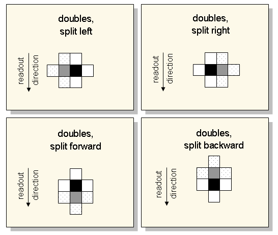
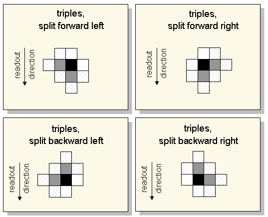
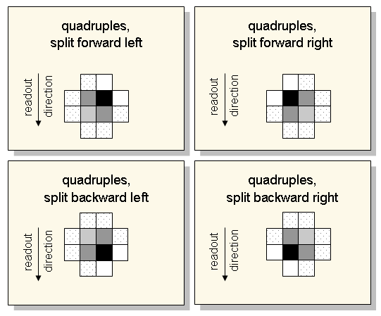
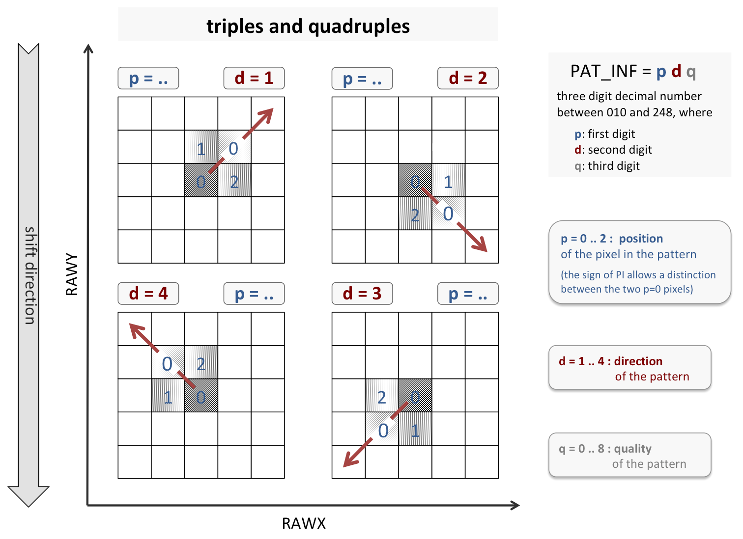
As seen from the main pixel (that with the maximum PHA value), the pattern may extend along four directions. The possible orientations of the symmetry axis (indicated by red arrows) are numbered from 1 to 4 and assigned to the second digit of PAT_INF. The first digit specifies the position of an individual pixel in the pattern: 0 if along the symmetry axis, 1 if left of it, and 2 if right of it. In the case of quadruples there are two pixels along the symmetry axis; they can be distinguished by the sign of PI. The third digit of PAT_INF indicates the quality of the pattern. This is defined as the number of direct neighbour pixels which might contain (with a low likelihood) PHA values of at least the minimum PHA value.
As seen from the main pixel (that with the maximum PHA value), the pattern may extend along four directions (indicated by red arrows). They are numbered from 1 to 4 and assigned to the second digit of PAT_INF. For the first digit, specifying the position of an individual pixel in the pattern, the same definition as for triples and quadruples is used for consistency reasons; thus this digit is always 0 here. As in the case for triples and quadruples, the two pixels can be distinguished by the sign of PI. The third digit of PAT_INF indicates the quality of the pattern. This is defined as the number of direct neighbour pixels which might contain (with a low likelihood) PHA values of at least the minimum PHA value.

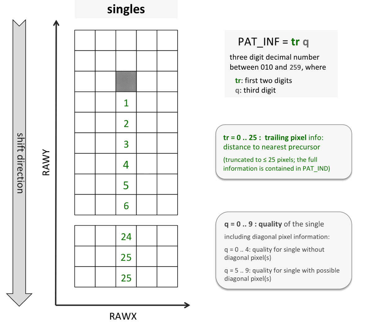
Because there is no orientation defined for singles, the first two digits in PAT_INF are used for another purpose: to code the distance (in pixels) to the nearest precursor (with a PHA value of at least the threshold for precursors along the shift direction. This information is useful for checking the influence of preceding charges on the CTI due to partial trap saturation. A value of 0 indicates a 'first single', i.e., a single which has no precursor in the same CCD readout frame. Values larger than 25 pixels need to be truncated to 25 pixels in order to stay within the limits of one byte. The third digit is used for the quality as for the doubles, triples, and quadruples, but, because for singles only values between 0 and 4 can occur, the definition is extended to highlight the 'isolated singles'. Isolated singles are defined as to have no charge in any of the four diagonal neighbours above the threshold for events next to singles in diagonal pixels. If there may such charge be present in at least one diagonal pixel, then 5 is added to the quality, so that values between 5 and 9 result.
For invalid patterns, PAT_INF contains the number of pixels in the pattern with PHA ≥ the threshold for MIPs.
The FITS column PAT_TYP, together with the column PI make very detailed selections possible in a straightforward way, as illustrated in the following examples.
Here a generic notation is used. If the selection is done with the FTOOL fselect, then the following coding needs to be applied:
| generic | coding in fselect | ||
|---|---|---|---|
| a = b | a .eq. b | a .EQ. b | a == b |
| a < b | a .lt. b | a .LT. b | a < b |
| a > b | a .gt. b | a .GT. b | a > b |
| a / b | floor(a/b) | ||
| mod(a,b) | a % b | ||
| a in [b:c] | a >= b && a <= c | a.ge.b .and. a.le.c | |
For a better understanding it may be helpful to keep the basic concept in mind:
| select | by specifying |
|---|---|
| valid pattern | PAT_TYP > 0 |
| invalid pattern | PAT_TYP < 0 |
| below threshold pixel (PHA < minimum PHA value) | PAT_TYP = 0 ( or PI = 0 ) |
| main pixel in pattern | PI > 0 |
| secondary pixel(s) in pattern | PI < 0 |
An additional selection is possible with the MIP precursor bit 18 in the FLAG column (which PATTERN sets to 1 for all of the pixels in the pattern if at least one of the triggering pixels is trailing a MIP):
| select | by specifying |
|---|---|
| most reliable spectral quality (no preceding MIP) | bit 18 = 0 |
| less reliable spectral quality (preceding MIP) | bit 18 = 1 |
This makes it straightforward to perform the following selections:
| select | by specifying |
|---|---|
| all pixels in patterns of n pixels | abs ( PAT_TYP ) = n |
| all pixels in valid patterns of n pixels | PAT_TYP = n |
| all pixels in invalid patterns of n pixels | PAT_TYP = -n |
| main pixel in patterns | PI > 0 |
| main pixel in valid patterns | PI > 0 && PAT_TYP > 0 |
| all pixels in patterns with total PI in range | abs(PI) in [PI_min:PI_max] |
| all pixels in valid patterns with total PI in range | abs(PI) in [PI_min:PI_max] && PAT_TYP > 0 |
| main pixel in patterns with total PI in range | PI in [PI_min:PI_max] |
| main pixel in valid patterns with total ~energy in range | PI in [PI_min:PI_max] && PAT_TYP > 0 |
If also PAT_INF is used, then additional selection criteria become available:
| select | by specifying |
|---|---|
| all first singles (i.e., with no precursor with PHA ≥ threshold for precursors) | PAT_INF / 10 = 0 |
| all trailing singles (i.e., with precursor with PHA ≥ threshold for precursors) | PAT_INF / 10 > 0 |
| all singles with precursor at 2 pixels distance | PAT_INF / 10 = 2 |
| all singles with precursor at >10 pixels distance | PAT_INF / 10 > 10 |
| (all pixels of) patterns with highest spectroscopic quality | mod ( PAT_INF, 10 ) = 0 |
| (all pixels of) forward split doubles | abs ( PAT_TYP ) = 2 && PAT_INF / 10 = 3 |
| preceding pixels of valid forward split doubles | PAT_TYP = 2 && PAT_INF / 10 = 3 && PI < 0 |
| left pixels of valid triples which are split backward-left | PAT_TYP = 3 && PAT_INF / 10 = 14 |
The following examples illustrate more specific selections:
| select | by specifying |
|---|---|
| all valid first singles in energy range with the highest spectroscopic quality and no charge ≥ threshold for events next to singles in diagonal pixels in any diagonal pixel | PAT_TYP = 1 && PI in [PI_min:PI_max] && PAT_INF = 0 |
| all valid first singles in energy range with the highest spectroscopic quality and charge ≥ threshold for events next to singles in diagonal pixels in at least one diagonal pixel | PAT_TYP = 1 && PI in [PI_min:PI_max] && PAT_INF = 5 |
| all valid first singles in energy range with possible charge ≥ minimum PHA value in one direct neighbour pixel and charge ≥ threshold for events next to singles in diagonal pixels in at least one diagonal pixel | PAT_TYP = 1 && PI in [PI_min:PI_max] && PAT_INF = 6 |
| preceding pixels of all forward split doubles with a total energy in energy range | abs ( PAT_TYP ) = 2 && PI in [-PI_max:-PI_min] && PAT_INF / 10 = 1 |
| preceding pixels of all forward split doubles with a total energy in energy range, omitting those with the highest spectral quality | abs ( PAT_TYP ) = 2 && PI in [-PI_max:-PI_min] && PAT_INF / 10 = 1 && mod ( PAT_INF, 10 ) > 0 |
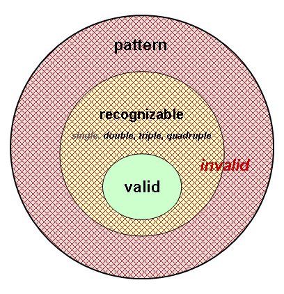
A pattern is the largest compound of pixels which share a common side (pixels which touch a corner of a pattern do not belong to the pattern). In theory, the maximum size of a pattern is only limited by the number of pixels in the CCD.
A recognizable pattern is one which exhibits a charge distribution that is consistent with what could have been created by the absorption of a photon and which shows no evidence of having been disturbed by other charge.
A valid pattern is a recognizable pattern which is sufficiently far away from an insensitive or disturbed area (CCD border, bad/bright pixel, MIP trail) to make it unlikely that its charge distribution is influenced by unknown charge released in this area.
In the case of eROSITA it is motivated to restrict the recognizable (and thus the valid) patterns to a maximum size of four pixels: to singles, doubles, triples, and quadruples.
While singles and doubles are by definition always recognizable, the situation is different for triples and quadruples. For the triples, the pixels have to form an L-shaped pattern, and the pixel with the maximum PHA value has to sit in the corner. Recognizable quadruples have to exhibit a square geometry and there is also a requirement on the charge distribution. The simplest requirement is that the pixel with the maximum PHA value is located diagonally opposite to that with the minimum PHA value. This criterion, however, is somewhat too restrictive; an improved criterion will be given below.
The diagrams here show all the cases of recognizable > 1 pixel patterns. Only pixels which are relevant for the pattern classification are displayed, and pixels containing charge PHA ≥ the minimum PHA value are shown in black or grey. The black pixel is that with the highest PHA value in the pattern.
The criterion for valid patterns is that for the dotted pixels information about their charge may be missing, but that it must be present for the white pixels down to the minimum PHA value.
The distinction between recognizable and valid patterns is based on the content in the dotted pixels: in order to be considered as valid, the charge in these pixels has to be known down to the minimum PHA value. Otherwise there might be charge present which would either make the pattern unrecognizable (so that the pattern should be ignored) or would lead to an incorrect reconstructed energy of the incident photon, because this charge would be missed. Recognizable, but invalid patterns occur at the CCD edges and near bad/bright pixels, or near MIP trails.
Due to the requirement that no direct neighbour of a pixel in a pattern must be located an insensitive pixel, each insensitive pixel creates an insensitive area around it where no valid patterns are found. The same happens for the CCD edge. Thus, e.g., singles at the CCD edges are not considered as valid.
For an efficient, compact transmission of the pixels which contain scientifically important information, a special telemetry format was developed. In short, all the pixels are transmitted which contain charge PHA of at least PHA_THR, a threshold which can in principle be set individually for each pixel. In "worthwhile" cases also the 8 pixel environment around such a pixel is transmitted, but for such environment pixels only a limited range of PHA values is available.
One consequence of this telemetry mode is the presence of pixels where only an upper limit PHA_UL of their PHA value is known: PHA < PHA_UL. If PHA_UL ≥ minimum PHA value, then these pixels are "white". Otherwise there is a possibility that they contain PHA ≥ minimum PHA value. This possibility, however, is low, because the interval [0:PHA minimum -1] is typically much larger than [PHA minimum:PHA_UL-1] and because the detector noise rises steeply towards 0. Thus, it is assumed that PHA < minimum PHA value for such pixels and they are also treated as "white" pixels. The fact that this treatment might be incorrect is propagated into the quality information for the pattern (contained in PAT_INF), which is increased for each such pixel by one.
Another consequence of this telemetry mode is the presence of pixels which occur only as an environment pixel and touch a corner of the central pixel. Such pixels do not belong to the pattern around the central pixel. They have to be ignored, i.e., treated as invalid singles, because they were only transmitted due to their coincidental neighbourhood to the central pixel. This implies that valid singles must be triggering pixels.

In order to distinguish between the different types of pixels, the following designations are used: T: triggering pixel, N: direct neighbour pixel, D: diagonal pixel. Thus, 'D' pixels without at least one 'N' pixel next to them have to be ignored.
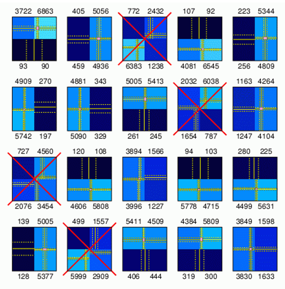
The simplest criterion for valid quadruples is that the pixel containing the maximum charge is located diagonally opposite to that with the minimum charge. This criterion follows directly from the assumption that the individual pixels intercept that part of a spherically symmetric charge cloud which falls into their area.
However, due to the finite energy resolution of the CCD, valid quadruples may violate this criterion somewhat. An improved criterion for valid quadruples is that the observed charge distribution in the pattern is consistent with that created by a single photon. The main challenge here is to consider statistical fluctuations in an algorithm which is reasonably fast.
Thus, a simplified algorithm is used: the center of the charge cloud is estimated independently from the ratio of the adu values in two horizontal and two vertical pixels of the pattern; if these estimates give a consistent result within the statistical uncertainties, then the quadruple is considered valid.
In the examples shown here none of the 20 quadruples satisfies the criterion that the pixel with the minium charge is located diagonally opposite to that with the maximum charge. Nevertheless, in 16 cases the reconstruction of the center of gravity gives a consistent position for the incident photon, if 1σ uncertainties are used, so that these quadruples are considered valid.